HOHOIST PLANS
HOHoist will allow you to build a large model railroad layout in your garage and
still be able to use it for your cars. HOHoist can easily lift a 10’ x 15’ (or larger) layout high enough to clear
any standard height vehicle. Raising and lowering the layout with HOHoist is easy and can be done with only one hand
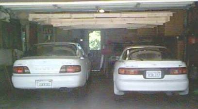
(though two hands are recommended.) Here are two pictures of HOHoist in operation:
HOHoist Raised:
HOHoist Lowered:
HOHoist uses standard off-the-shelf components. The lifting mechanism is
comprised of industrial steel roll-up door parts, and the remaining parts can be purchased at any full service home
supply store such as Home Depot or Orchard Supply & Hardware.
You should read this entire document before attempting to construct an HOHoist
because there are some subtle geometry issues that must be handled correctly. Also, be sure you understand the diagrams
and pictures before you start construction since it will be time-consuming to de-install HOHoist if basic changes are
needed.
HOHoist has 3 types of parts: the overhead door parts, the pulleys and
associated parts, and the materials required to build the layout table grid. These plans make no assumption about how
you build your layout table top; the plans for the layout table grid will work for a plain flat top constructed from
sheets of plywood or fiberboard, or you can use a grid system to provide support only directly under your track.
The overhead door parts are high quality industrial grade components that have far more weight
carrying capacity than any model railroad layout. These parts are the same ones used to lift roll-up steel doors in
large warehouses; these doors can weigh many hundreds of pounds.
|
Part Name/Description
|
Qty. Req’d
|
Photo #
|
Notes
|
|
15’ of 1” diam. steel shaft with ¼” keyway
|
1
|
6.1
|
The length of the shaft is determined in step 3.2. Shafts come in lengths
up to 23’.
|
|
WD-5 cable drum (left)
|
3
|
6.2
|
Left & right spools look similar, but the cable grooves go in opposite
directions
|
|
WD-5 cable drum (right)
|
3
|
6.2
|
|
|
¼” x 1’ keystock
|
2
|
None
|
|
|
SP-2 bearing bracket with ball bearings
|
4
|
6.3
|
Note the 90 degree holes in the bracket for mounting purposes.
|
|
Collar sleeve (1” dia.)
|
2
|
None
|
Prevents lateral shaft movement
|
|
3-to-1 chain operator
(Part # 9-8-1)
|
1
|
6.4
|
This is the 3 – 1 reduction drive unit used to turn the shaft and
raise/lower the layout
|
|
“Long” pre-looped 5/32” cable
|
4
|
6.5
|
See Sect. 3.1 for cable length calculations
|
|
“Short” pre-looped 5/32” cable
|
|
|
See Sect. 3.1 for cable length calculations
|
You should be able to purchase all of the above parts for about $300.00. Shipping costs and tax
(if applicable) are extra.
HOHoist requires a total of 10 pulleys and the means to attach them. 4 of the pulleys are attached to
the “ceiling” (or whatever you have up there) and 6 are attached to the layout table. The pulleys are all 2 ½” in
diameter so they do not require the cable to loop around too tight a diameter. It is convenient if the pulleys have
removable shafts; this way you can easily put the cable through the pulley by removing the shaft and wheel, inserting
the cable in the pulley sheave, and then reinstalling the pulley wheel and shaft. Pulley’s like this cost about $7.00
each and are available in any large home supply store. The 6 pulleys that attach to the layout table do so by means of
J-shaped brackets called truck hooks. These come in various sizes and are available in most large hardware stores.
Picture 6.9 shows one pulley and it’s truck hook, plus the bolts used to attach the truck hook to the layout table.
The 4 upper pulleys attach to the ceiling, rafters, joists, etc. by a simple screw-in or bolt-through hook. Be sure to
get hooks sufficiently large (3/8” or larger) since each hook will be supporting roughly 1/6th of the total
weight of your layout. You will also need six sets of cable clamps. These clamps are usually packaged 3 clamps to a set,
and sell for about $3.00 per set in almost large hardware or home supply stores. Get clamps sized for 1/8” cable. You
will need these clamps to manually adjust the length of each cable.
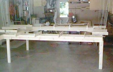
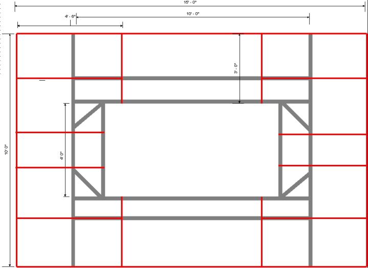
Picture 6.11 is a diagram of the layout table grid shown in the other pictures. The grid is made from
two types of lumber: 1 x 6’s and 1 x 4’s. In Picture 6.12 the 1 x 6’s are gray in color and appear wider than the
red 1 x 4’s. Actually they are the same width; the wider width on the diagram is to help you visualize the 1 x 4’s
sitting on top of the 1 x 6’s. For the 10’ x 15’ table shown in this document a total of seven 10’ 1 x 6’s are
needed. Because the lengths of the 1 x 4 pieces are much shorter you can get fewer longer ones or more shorter ones,
depending on how much sawing you like to do. You also need 4 legs to support the table when it is lowered. 2 x 4 lumber
is a good choice because it is both inexpensive and strong. Each leg attaches to the 1 x 6 sidemember using a small
hinge. Each leg is braced using a metal brace secured to the leg with a lag bolt and to the layout table using a bolt
and wingnut. Picture 6.12 shows the top of a leg and the hinge attaching it to a 1 x 6 sidemember. The leg brace shown
in picture 6.12 is 24” long. It was cut with a hacksaw from a piece of 2” x 96” x 1/16” aluminum stock bought at
a home supply store for about $8.00.
The table shown in the pictures at the beginning of this document is about 10’ x 15’ in size. It
is as large as possible for the standard 2-car garage in which it is installed, given that the garage has a 4-section
folding door that takes up about 8’ of length when it is raised. If the garage door were of a different type (say, a
single piece door that opened out) the layout table could have been larger. The size of the table is critical in
determining how to install HOHoist and how to determine the length of the cables and the shaft. The reason for this
should become clear based on the following diagrams:
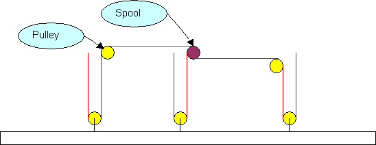
Top View
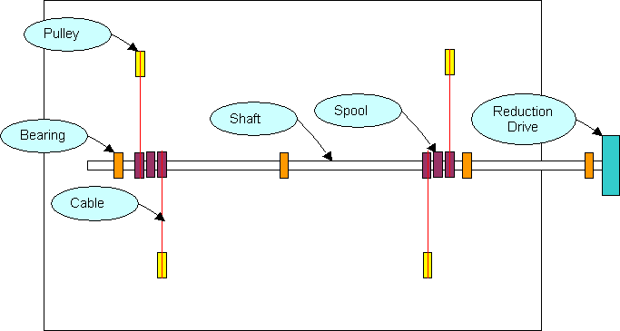
In this view you see the shaft with all its components above the layout table. Notice that the 4 yellow pulleys are
positioned roughly ¼ of the way from the long edge of the table. The overall effect is to have the 3 cables on each
side span about 25% of the table width. Cables run from the outside spools over these pulleys and down to the table. The
cables from the center spools run directly down to the table. As the table gets larger, the distance between the two
outboard pulleys on each side gets larger, and the cables running over them must therefore be lengthened accordingly.
Not shown on the above diagram are the collar sleeves. These two pieces need to be placed on opposite sides of one of
the bearings. The collar sleeves prevent the entire shaft assembly from shifting laterally. This is important, since if
the shaft moves out of alignment with the reduction drive unit, the motorcycle-type chain that connects them will come
free and the shaft will be free to rotate and drop the layout table. You can get a better idea of how the table size
affects the cable length by looking at the side view diagram below:
Side View
Here you see the 5 pulleys on one side of the table. The other side looks the same. Notice that, for the two outboard
cables, the overall length of the cable is measured from the spool, across the top pulley, down to the table, and back
up to the same level as the top pulley. If the table is roughly 10’ wide, then the top pulley will be about 2 ½’
from the center shaft & spool. And if the table, when it is lowered, if 4’ below the shaft, then there is a total
of 2 ½’ + 4’ + 4’ = 10 ½’ of cable, not counting the length of cable required to wrap around the pulleys
(negligible) or as extra wraps around the spools (not negligible). The center cables are simpler since they just run
down to the table and back up. In the above example, these cables would be 4’ + 4’ = 8’ long, plus the additional
length required to wrap around the bottom pulley and the extra wraps around the spools. When the table is lowered you
want to have about 3 wraps of cable left on the spools. This is because the first wrap of cable around the spool is
right at the edge of the spool and you want to make sure there is no chance of a cable mis-wrapping as the layout is
lifted. Also, it’s a good idea to have some “extra” cable to make it easier for the final leveling process. Since
the spools are 5” in diameter there is about 16” of cable required for one wrap, so 3 extra wraps = 48” = 4’. So
to calculate the length of the 4 long cables, start with 4’ and add twice the distance from the lowered table top to
the shaft, plus the distance between the shaft and the upper pulleys. The two short cables are 4’ + twice the distance
from the lowered table top to the shaft.
If you look at the Top View diagram above you will see that the shaft must be long enough to reach
from the reduction drive sprocket to the farthest outboard spool. The shaft does not need to extend to the far side of
the layout table. The actual length of the shaft will be determined by how close (or far) from the first spool you mount
the reduction drive unit, how wide your table is (this determines how far apart the two sets of spools are), and where
you are able to mount the ball bearing brackets. In general you want the shaft to be as short as possible, with the
bearing brackets mounted close to the spools and the chain sprocket. The side view diagram above shows 4 brackets, but
in fact you may need more if your shaft is longer. The shaft itself is quite rigid (1” diameter solid steel) but it
will flex a little if the distance between bearings is more than 3’ – 4’.
As noted above, the cable lengths are directly related to far below the shaft the lowered table is.
This distance is determined by how high off the floor you want the table to be (when it is lowered), and by how high
your shaft is when it is mounted to the ceiling, rafters, or whatever holds it up. Model railroad layouts are often
about 40” off the floor, but you can obviously make yours any height you want. The layout table height is something
you must decide on, however, before you can calculate the length of the cables (or the length of the legs that hold up
the table when it is lowered.)
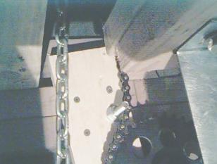
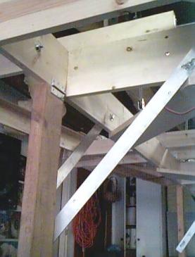
If you look at picture 6.4 showing the Reduction Drive you will see that it must be mounted using
only it’s back surface. This is because the bearings that support the large chainwheel protrude from the sides of the
operator housing. Consequently you may have to build an attachment bracket on one sidewall to hold the chain operator.
Picture 6.8 shows the chain operator attached to a bracket made from 2x4 lumber that is in turn attached to the garage
sidewall. Note that the shaft must extend to and be centered directly below the chain operator so the large sprocket on
the end of the shaft is directly below the small sprocket located inside the chain operator housing.
Figures 6.7 and 6.8 show two bracket attachments. One bracket is placed close to the operating
sprocket, one close to each set of spools, and one roughly mid way between the two sets of spools. This bracket
placement is also shown on the top view diagram above. Because the shaft is so strong, bracket placement is not really
critical. However, it is best to place the brackets close to the main points of stress, which are the sprocket and the
spools. The “middle” bracket is located about half the distance between the two spool brackets simply to help
stabilize the shaft.
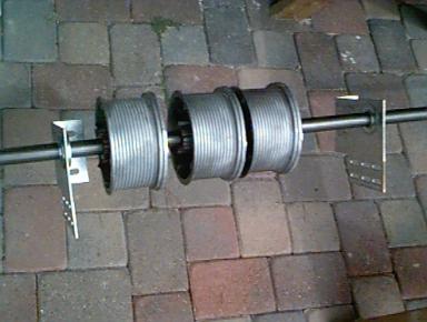
When you install the shaft assembly you must have all of the shaft’s parts placed correctly on it
since you cannot remove any part once the brackets are in place. The key to correct pre-assembly of the shaft is the top
view diagram above. Be sure to make a diagram like this before you attempt installation. The relationship between the
brackets, spools, and sprocket may be different for your situation, but your diagram should show all of the spools,
brackets, the two collar sleeves on opposite sides of one bracket, and the sprocket. Note that the Top View diagram
above does not show the two collar sleeves. The most important thing is to ensure you have the spools mounted correctly
on the shaft. To do this, first group the three left and three right spools together. Next, arrange the spools in each
group so they all face the same way (like the spools in picture 6.8.) Now visualize how the cable will wrap around the
spools. What you must avoid is putting the spools on the shaft backwards, i. e., in such a way that the cable wraps one
way on one set of spools, and the opposite way on the other set. If you do this you will have to disassemble the entire
shaft and start over. If you aren’t sure which way to put the spools on the shaft, take two cables and wrap them
around one spool in each set. You should be able to see how the spools need to be put on the shaft so the cable wraps in
the same direction on each set of spools. Also, look at the side view diagram, and note how one of the spools on each
set wraps from the bottom, and the other two wrap from the top. This may look peculiar, but if you imagine the shaft
turning and the cable wrapping (or unwrapping) you will see that this is the way it has to be. If you think you have to
put one spool in each set “backwards” compared to the other 2, you are wrong. Do not do this. Instead, look at the
diagrams again, and try putting cables through all the spools on one side and turning the shaft by hand. Each spool has
two thumbscrews that tighten against the shaft. Leave these loose for now because later you will have to move the spools
laterally on the shaft to get the aligned properly.
You have to have at least the bottom layer (built from 1 x 6 lumber) of the layout table built to
enable you to determine where to mount the four hooks the hold the upper pulleys. If you want, you can mount the shaft
and all its parts before the table grid is built, but you cannot locate the hooks that hold the upper pulleys or do
anything with the cables until you have the table with its pulleys and truck hooks available. The key to the layout
table grid design is the location of the truck hooks. These must be directly beneath the hooks that support the upper
pulleys. Depending on how these hooks are attached (and to what they are attached) you may have to change the size/shape
of your table grid. Again, depending on your particular situation, you may have to add support structure to your garage
to hold the upper pulley attachment hooks. Keep in mind that each of these hooks will support about 1/6th of
the total weight of your layout table, so it is important to locate them properly and ensure they have the required
weight bearing capability.
Before you install the shaft be absolutely sure you have all the components mounted on the shaft in
the proper orientation. Once the shaft assembly is ready you must either have existing supports to attach the bearing
brackets to, or build suitable supports. Picture 6.7 shows such a support. Once the structures for attaching the bearing
brackets are ready, you simply lift the entire shaft assembly up to the proper level and attach the bearing brackets to
the support structures. If the support structures are wood you can use 3” drive screws to do this. What is important
here is ensuring the bearing brackets are all level and in line so there is no horizontal or vertical displacement
forces on the shaft. If you have installed the brackets properly you should be able to use one hand to turn the shaft;
it should turn easily and smoothly in the brackets with no sense of resistance.
The Reduction Drive unit is what you will use to operate HOHoist. Consequently, it needs to be
installed in a location that provides enough room to stand next to it while the layout table is raised or lowered. Also,
keep in mind the long loop of chain that hangs down from the unit must be free of obstructions or things it could catch
on. When installing the Reduction Drive unit, place it directly above the sprocket on the end of the Shaft, and as far
above as possible so you have no slackness in the motorcycle-type chain that connects the small sprocket on the
Reduction Drive to the large sprocket on the Shaft. If there is slack in this chain you will have to install a tensioner;
the following picture shows a single 2” bolt used for this purpose:
Once the shaft is mounted, locating where the pulley hooks go is easy. What can be hard is building
the structure required to support the hooks. This depends on where the hooks have to be, and this in turn depends on the
size and shape of your layout table. Note that there are only 4 pulleys (the four outboard locations) but 6 pulley
hooks. This is because the center cable on each side descends directly from the center spool on each side, goes through
the center pulley on the layout table, and then is attached near the spool to a hook just like the hooks that hold up
the 4 outboard pulleys. Put the layout table on its legs under the shaft in the position you want it to be after the
cables are attached. Using a ladder and a plumbline, identify locations above the table where the four upper pulleys
must be located. To see how to do this, look at the top view and side view diagrams and note how the four pulleys (and
hooks) are spaced relative to the layout table side members. It is important to use a plumbline to locate the pulley
hook attachment points because the table will be heavy and gravity will require the cables supporting it to be as
vertical as possible. Once the 6 pulley hooks are ready, hang one pulley from each one. Next, using the plumbline
locations, mount the 6 truck hooks to the layout table and connect one pulley to each. Now you are ready to string the
cables.
Start by separating the 4 long cables from the 2 short ones. On each set of spools, the two long
cables are attached to the two outer spools, and the short cable is attached to the inner spool. It’s obvious how you
thread the end of the cable with the small block crimped on it through the spool, and then simply wrap the cable around
the spool, being careful to ensure the cable fits nicely into the grooves cast in the spools. You want about 3 – 4
wraps of cable around the spool before you take the free end through the upper pulley and then down to the table. During
this process the spool set screws should be loose. Notice that each spool has 2 set screws and a keyway. While you are
stringing the cables through the spools you will probably have to slide the spools sideways on the shaft to have enough
space to pull the cable end through the small slot on the edge of the spool. After this is done, rotate the spool on the
shaft so the keyway lines up with the keyway slot milled in the shaft. When all the spools have their cables attached,
move them close together and, keeping them lined up with the keyway, install the keyways by inserting them into the slot
milled in the shaft, and then pushing them along the shaft until they have secured all the spools. You will probably
have to use a small hammer to tap the keyways into place. After the keyways are in place, tighten the set screws. The 3
spools on each side should be close together, with no more than about ½” space between them. If they are far apart
the cables will run at too great an angle relative to the face of the spool, and the cable will not wrap smoothly on the
spool. Picture 6.8 shows what one set of spools looks like during the cable stringing operation. To finish stringing the
cables you will run each cable down through the pulley on the table that is directly beneath it, and back up to the hook
above the pulley. Loop the free end of the cable around the hook and pull down on it to make it tight. The pre-made loop
on the end of the cable is not used; instead, attach 2 or 3 cable clamps to the cable and tighten them while the cable
is held taught. See Figure 6.14 for a picture of how a finished cable looks.
You are now ready to raise the table for the first time. Do this very slowly and carefully, paying
close attention to smooth wrapping on the spools and any lateral shaft movement as the cables wrap up on the spools.
Carefully watch the end of the shaft as the cables wrap up. Stop immediately if the shaft moves laterally more than ½”
or so. If the chain slips off large sprocket on the end of the shaft the entire table will fall. If the cables don’t
wrap smoothly on the spools, or if the shaft tends to move laterally, you probably have the cables at too great an angle
to the spools. To fix this you have to either move the spools or the pulleys through which their cables run to get them
in better alignment. In general you want to position the spools, pulleys, and hooks so their centers are all lined up;
doing this will minimize lateral forces on the spools (and the shaft) as the table is raised. See the Top View diagram
for the proper arrangement. You know you have everything in position when you can raise the table to its upper-most
height and (1) all cables wrap smoothly on their spools, and (2) the shaft does not move laterally.
The purpose of the collar sleeves is to keep the shaft from moving laterally. Why have the collar
sleeves at all if you have completed Step 5.1 properly? The reason is, if anything causes the operating chain to
disengage from either sprocket, the table will fall. The collar sleeves ensure the shaft and its sprocket remain in
alignment with the Chain Operator sprocket. Once you have Step 5.1 completed simply move the collar sleeves adjacent to
the bearing bracket that is between them, and tighten them. This will ensure the shaft cannot move laterally and will
keep the operating chain sprockets in good alignment.
Your HOHoist should now be ready for normal operation. A final check is to slowly raise and lower it
several times, paying careful attention to how the operating chain wraps around the sprocket on the end of the shaft.
Pay particular attention when raising the table since this puts maximum tension on the working side of the chain. If the
non-working side of the chain does not wrap smoothly around the sprocket, the sprocket may slip a tooth and the table
will drop one tooth’s distance. This is not a serious problem, but it is disconcerting. If this happens you will need
to install some sort of chain tensioner; see the picture is Step 4.4 for an example of this.
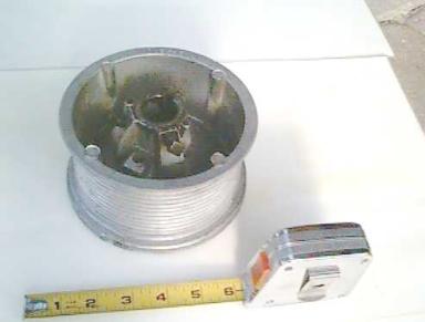
A cable spool Note that the spool has grooves cast in its surface. These grooves allow the cable to wind smoothly onto
the spool. There are “left” and “right” spools for use on opposite ends of the shaft.
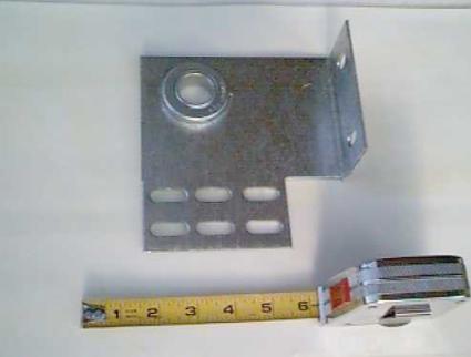
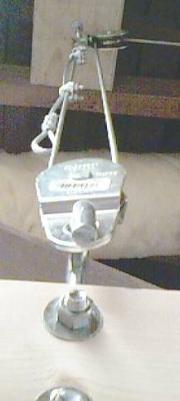
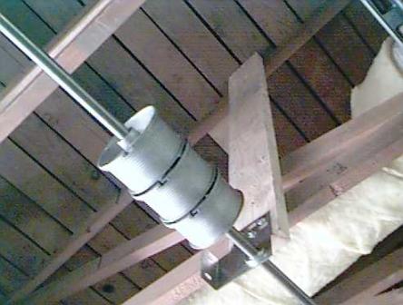
The bracket attaches to your garage joists and holds the ball bearing through which the shaft fits.
The bearing enable the shaft to turn easily, regardless of how much weight it supports.
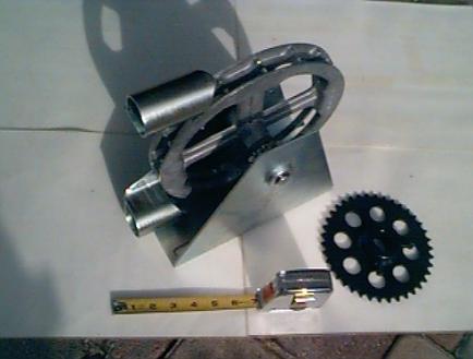
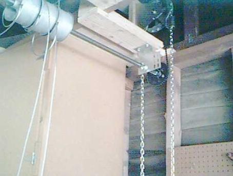
Not shown is the long aluminum chain that drives the large pulley at the top of the picture, and
the smaller motorcycle-type chain that connects the small sprocket on the large pulley shaft to the driven sprocket
shown at the bottom.
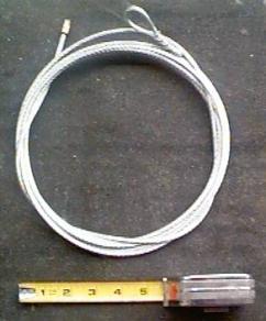
Note that the cable has a small brass block crimped on one end; this fits into a slot on the cable
spool. The other end of the cable has a loop, but this is not used. Instead, the free end of the cable is adjusted
manually using separate cable brackets.
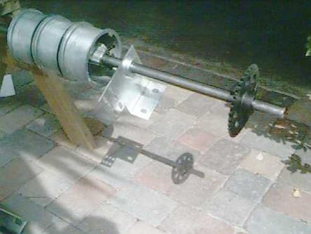
Note that the sprocket is placed near the end of the shaft, and one of the brackets will be
positioned near it to counteract the stress induced by sprocket.
Note that the bracket is screwed onto a 2x6 piece of lumber that in turn is screwed to the roof joist
in three places. The small blocks crimped on the ends of the cable go through the short slots in the outside edges of
the drums.
Notice the long aluminum chain that is used to raise/lower the layout table. The short
motorcycle-type chain connects a small sprocket just inboard of the large aluminum chain pulley to the operating
sprocket mounted on the end of the shaft.
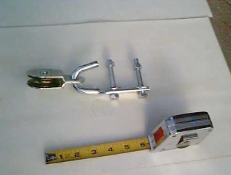
The pulley eye is a good fit for the diameter of the 4” truck hook. The bolts through the truck
hook attach it to the layout table framework.
This picture was taken before the cable lengths were adjusted. Note also the “upper” 1 x 4 lumber
sitting on top of the underlying 1 x 6 pieces.
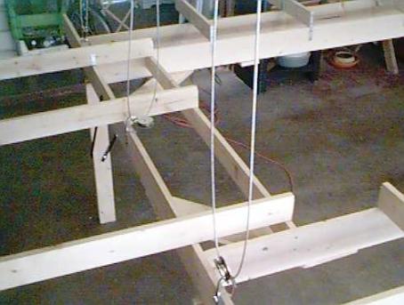
This is just on idea you might use for your layout table grid. You can make your table any size or
shape you want; the only requirement is there be three sturdy attachment points on each side for the truck hooks and
pulleys.
The table leg is the vertical dark piece of wood (2x4) attached by a hinge to the 1x6 layout table
grid. Note that the 1x6 sits directly on top of the leg. This leg has 2 aluminum braces; note the thumbscrew (top right)
that makes it easy to attach/detach the brace to/from the layout table grid.
Top view of the leg shown in 6.12 along with the pulley and truck hook located near it.
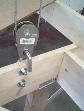
This picture shows a view looking up from one of the truck hooks. Notice how the upper pulley hook is
also used to attach the free end of the cable, and how the cable clamps are attached.